

How regenerative braking affects rail power supply design
Dr. Alistair Thorne
Time
Click Count
Regenerative braking changes rail power supply design by introducing power flows from trains back into the traction network. The supply must accommodate both accelerating trains that draw current and braking trains that inject it. Whether that recovered energy reduces electricity purchases depends on the available receiving loads, electrical connections, voltage limits, and operating timetable.
For project managers, the first decision is whether the network can absorb enough braking energy without additional equipment. A busy metro may reuse much of it through nearby accelerating trains. A lightly operated line, an electrically isolated section, or a route with sustained downhill braking may require reversible substations or energy storage to capture more. Regeneration can improve energy performance, but it does not automatically justify smaller substations or eliminate the need for a dependable alternative braking path.
Start with network receptivity, not the train’s recovery rating
A train’s ability to generate electricity during braking establishes the potential energy available. Network receptivity determines how much of that energy can actually leave the train. The distinction matters when evaluating rolling stock efficiency claims: energy generated at the traction motors, energy returned through the collector, and energy avoided at the utility meter are different quantities.
In a DC traction system supplied by conventional diode rectifiers, power can flow from the AC supply into the traction network, but the rectifiers do not provide a return path to the upstream AC system. Regenerated energy can still supply other trains and suitable loads connected to the same electrical network. If those loads cannot absorb the available power, traction voltage rises. The braking train then reduces regeneration or transfers braking effort to another available system, such as onboard resistor braking or friction braking, according to its control strategy.
Electrical proximity matters as much as physical proximity. Two trains at neighboring stations may sit in different feeding sections, while more distant trains may share a usable power path. Sectioning arrangements, conductor resistance, return circuits, and switching states all affect the transfer. A receiving train does not guarantee full recovery if the voltage at the braking train reaches its control limit before the energy can reach that load.
Timetables introduce another constraint. Short headways create more opportunities for braking and acceleration to overlap, but regular departures alone do not establish receptivity. Directional demand, station spacing, dwell times, gradients, and train loading change the balance. At a terminus, several trains may brake within a short interval while few trains accelerate nearby. A disrupted service can produce a different power-flow pattern from the timetable used for the original design.
AC electrification can offer a wider path for regenerated power through the traction supply and potentially into the upstream network. Acceptance still depends on substation topology, feeding-section connections, utility requirements, and protection arrangements. Phase separation and other electrical boundaries restrict where power can move. A project should establish the actual return path before treating the upstream grid as an unlimited energy sink.
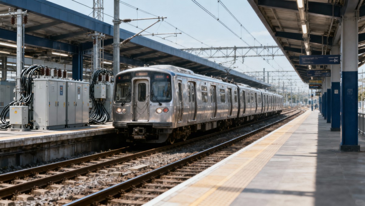
Voltage limits shape both energy recovery and equipment design
Regeneration raises voltage at the train’s connection point because current must flow from the train toward a receiving load. The rise depends on injected current and the impedance of the intervening circuit. A system can therefore have spare receiving capacity elsewhere while remaining unable to accept all the braking power at a particular location.
This creates a design tradeoff. Stronger electrical connections can support energy transfer and reduce voltage excursions, but larger conductors, additional feeders, or revised substation spacing require investment. The value of those changes should be assessed against their wider benefits, including acceleration performance and voltage support. A low resistance path improves transfer efficiency; it cannot absorb surplus energy by itself.
Control settings must also work together. Train regeneration thresholds, reversible-converter settings, storage charging thresholds, and substation voltage characteristics determine which device responds first. Poor coordination can cause regeneration to be curtailed while receiving equipment remains available, or allow devices to interact in ways that produce unstable voltage behavior. These settings need a system-level basis and sufficient margin for measurement tolerance, communication delays where relevant, and changing network conditions.
Supply-voltage requirements such as those addressed by EN 50163 and IEC 60850 provide an important reference for the permitted operating envelope. They do not, by themselves, establish an energy-management strategy. The project must translate the applicable voltage requirements into coordinated equipment limits, control thresholds, and acceptance criteria, using the editions and national requirements specified for the railway.
Regeneration also changes the electrical duties that equipment must withstand. Cables, switchgear, converters, and return circuits need assessment for current direction, thermal loading, fault behavior, and switching conditions. On DC systems, return-circuit potential and stray-current performance deserve attention. The location and direction of traction currents change during braking, so an assessment based only on trains drawing power can miss relevant conditions.
Protection studies must consider the behavior of each connected converter and source. A reversible substation or storage installation may alter fault contributions and isolation requirements, depending on its topology and controls. Adding an energy-recovery device therefore requires more than a capacity calculation: it also requires a clear account of how the installation detects faults, disconnects, and behaves when communications or control functions fail.
Choose the receiving path to match the operating problem
Three approaches can improve the use of recovered energy: increase transfer between trains, provide a path back to the AC network, or store energy for later use. They solve different problems, and a project may combine them. Selection should begin with the location, duration, and frequency of rejected braking energy.
Direct transfer between trains
Where accelerating trains provide sufficient demand, direct reuse avoids the additional conversion stages associated with storage or grid export. Timetable coordination and changes to feeding connections may improve recovery, provided they remain compatible with service capacity, isolation, and maintenance requirements.
The limitation is dependence on concurrent demand. A timetable adjustment that improves overlap during normal service may deliver little benefit during disruption or sparse operation. Electrical interconnection can expand the receiving area, but it can also affect fault levels and protection boundaries. Both the energy gain and the operational consequences need to appear in the comparison.
Reversible substations
A reversible substation provides a controlled path for surplus traction energy to reach the AC side. This can be attractive where surplus braking energy occurs frequently and the upstream system permits reverse power flow. The recovered energy may offset other site demand or be exported, depending on the electrical arrangement and commercial agreement.
Converter capacity should reflect the time profile of surplus power. Brief peaks and sustained downhill braking create different thermal duties. The specification should identify permissible overloads, operating duration, efficiency over the expected load range, harmonic performance, reactive-power behavior, and response when the AC network cannot accept export.
Technical export capability does not establish financial value. Metering arrangements, export permissions, tariff treatment, and connection costs influence the business case. Energy credited at a different rate from purchased electricity must be valued accordingly. A proposal based on applying the full purchase tariff to every exported kilowatt-hour may overstate savings.
Wayside energy storage
Storage separates braking from reuse in time. It can absorb a braking pulse and discharge when a subsequent train accelerates, potentially supporting traction voltage and reducing demand at the supply point. It is particularly relevant where useful receiving loads appear shortly after braking but are absent during the braking event itself.
Power and usable energy capacity require separate calculations. The installation needs enough charging power to accept the relevant pulse and enough available capacity to hold it. A large energy rating offers little benefit if the converter cannot accept the braking power. Conversely, a powerful converter cannot recover energy when the store is already at its operating limit.
Technology selection follows the duty cycle. Frequent short pulses place emphasis on power capability, cycling durability, and thermal management. Longer periods of imbalance increase the importance of energy capacity. The lifecycle assessment should include conversion losses, auxiliary consumption, degradation, replacement, maintenance access, and the applicable safety provisions.
Storage controls may serve several objectives that compete for capacity. Demand reduction, voltage support, and braking-energy recovery can require different charge states. The project should define their priority rather than assume all advertised benefits will occur simultaneously.
Use operational simulation to set ratings and acceptance criteria
The central engineering tool is a time-based traction power study that couples train movement with electrical network behavior. It should represent acceleration and braking characteristics, gradients, train mass, timetable operation, conductor impedance, substation behavior, and regeneration controls. Where storage or reversible converters are proposed, their limits and control responses must also be represented.
A useful study follows energy through the system. It distinguishes energy available from braking, energy injected into the traction network, energy received by other trains, energy sent into storage or the AC network, losses, and energy rejected. Reporting only a train-level recovery percentage leaves the project team unable to judge the effect on purchased electricity or equipment loading.
The assessment should include conditions that could change the investment decision:
- Peak service, sparse service, and credible timetable disruption.
- Different train loading and braking behavior on relevant gradients.
- Feeding arrangements used during maintenance or a substation outage.
- Storage at its charge limits or unavailable, and export temporarily restricted.
- Changes in voltage settings and control response within permitted tolerances.
These cases also explain why average energy savings cannot be used directly to reduce substation ratings. Regeneration may lower net electricity consumption while leaving the maximum coincident acceleration demand largely intact. Dependable supply capacity must satisfy the required service and contingency conditions. Any proposed reduction needs evidence that the supporting energy source remains available during those conditions.
Standards compliance should be organized around the interfaces affected by the change. Alongside supply-voltage requirements, relevant work may include electrical safety and return-circuit provisions under EN 50122-1, electromagnetic compatibility under the EN 50121 series, and applicable rolling-stock and supply-system coordination requirements. EN 50126 provides a framework for reliability, availability, maintainability, and safety activities. The contractual standards schedule must identify which requirements apply to the particular railway and equipment.
Acceptance testing should then test the intended behavior, including transitions between energy paths. Demonstrating that a converter can accept power in isolation is insufficient if train controls curtail regeneration before it responds. Tests should address representative braking events, voltage control, storage limits, loss of export capability, and equipment unavailability. Meter boundaries and measurement intervals must be agreed before energy-performance guarantees are evaluated.
The strongest investment case connects a measured or modeled operational problem to a specific receiving path. It shows where braking energy is rejected, how the proposed equipment captures it, and what that energy is worth after losses and lifecycle costs. Where a proposal cannot distinguish train-level recovery from savings at the electricity meter, the project has not yet established the benefit of changing its rail power supply.
Search News
Industry Portal
Hot Articles

Popular Tags
Recommended News
 Nov 02, 2026How regenerative braking affects rail power supply designExplore how regenerative braking shapes rail power supply design. Learn how voltage limits, reversible substations, and energy storage affect recovery—and smarter investment decisions.
 Nov 01, 2026Choosing switchgear for urban transit by short-circuit ratingChoose switchgear for urban transit with confidence. Learn how to verify short-circuit ratings, AC/DC fault duties, and protection timing to improve safety and service reliability.
 Aug 10, 2026How Is Traction Power Sized for High Speed Rail Speed, Load, and Route Demands?Traction power for high speed rail starts with timetable, load, and route demands—not just top speed. Learn how engineers size substations, margins, and peak capacity for reliable performance.
 Jul 29, 2026Railway Circuit Breaker Wholesale: How Buyers Compare Suppliers, Specs, and CostRailway circuit breaker wholesale buyers compare more than price. Learn how to assess suppliers, certifications, specs, lead times, and total cost to choose reliable rail protection solutions.
![]() Jul 06, 2026How to Evaluate a Railway Transformer OEM: Certifications, Testing, and Supply CapacityRailway transformer OEM selection goes beyond price. Learn how to assess certifications, testing, and supply capacity to reduce project risk and choose a reliable partner.
 Jul 05, 2026What to Check Before Comparing Traction Power Suppliers for Rail and Metro ProjectsTraction power suppliers should be compared on compliance, integration, reliability, and lifecycle cost—not price alone. Learn the key checks before selecting the right rail or metro partner.
 Jul 03, 2026How to Choose a Medical Air Compressor Supplier for Hospitals and Dental ClinicsMedical air compressor supplier selection starts with compliance, air purity, uptime, and service support. Learn how hospitals and dental clinics can reduce risk and choose with confidence.
 Jun 23, 2026DC Chargers Selection Guide: Power Levels, Connector Types, and Installation NeedsDC Chargers selection guide covering power levels, connector types, and installation needs. Learn how to match infrastructure, compliance, and uptime goals for smarter deployment.
 Jun 18, 2026High Speed Rail Power Demand 2026: Grid Load Drivers, Substation Needs, and Planning RisksHigh speed rail power demand 2026 is reshaping rail planning. Explore grid load drivers, substation bottlenecks, and key risks to avoid costly delays and underbuilt power capacity.
 Jun 14, 2026How to Select Industrial Pumps: Flow Rate, Head, Fluid Type, and Maintenance FactorsIndustrial pumps selection starts with the right duty point. Learn how flow rate, head, fluid type, and maintenance factors affect performance, cost, and supplier choice.
 Jun 10, 2026Radiators for Rail Power Systems: How to Compare Types, Capacity, and Maintenance NeedsRadiators for rail power systems compared: explore types, cooling capacity, and maintenance needs to choose reliable, cost-efficient solutions for demanding rail applications.
![]() Jun 09, 2026ESS for Rail Power Systems: Key Sizing Factors, Duty Cycles, and Integration LimitsESS for rail power systems: learn the key sizing factors, duty cycles, and integration limits that shape performance, lifecycle value, and smarter project decisions.
 Jun 07, 2026EV Charging Sourcing Checklist: Supplier Capacity, Compliance, and Cost RisksEV Charging sourcing checklist for buyers: assess supplier capacity, certifications, and hidden lifecycle costs to reduce risk, protect delivery, and choose with confidence.
 Jun 01, 2026Why are utility scale projects hard to connect?Utility scale projects face grid bottlenecks, complex studies, permitting delays, and rail power risks. Learn how to reduce connection delays and protect delivery.
 Jun 01, 2026Do photovoltaic systems pay off after incentives drop?Photovoltaic systems can still deliver ROI after incentives drop—learn how costs, self-consumption, tariffs, and risk planning shape smarter solar investments.
 May 23, 2026What rail carbon neutrality means for future investmentRail carbon neutrality is reshaping future investment. Explore a practical checklist for lifecycle emissions, standards, energy efficiency, and resilient rail asset value.
 May 16, 2026Is rail carbon neutrality realistic without grid upgrades?Rail carbon neutrality sounds achievable, but without grid upgrades it often falls short. Discover the infrastructure, power, and strategy gaps shaping realistic rail decarbonization.
 May 03, 2026EPC rail contractors: the risk points hidden in turnkey bidsEPC rail contractors may make turnkey bids look simple, but hidden risks can drive major overruns. Discover the scope, compliance, interface, and lifecycle traps financial approvers must check.
 Apr 23, 2026Traction power failures rarely start where they appearTraction power failures rarely start where they appear—discover how rail standards, predictive maintenance, rolling stock, signaling systems, and track maintenance shape rail transit efficiency.
 Apr 23, 2026Traction power supply upgrades can expose legacy weak pointsTraction power supply upgrades can expose hidden risks across signaling systems, rolling stock, ETCS, CBTC, and track maintenance. Learn how predictive maintenance and rail standards improve rail transit efficiency.
 Apr 23, 2026Substation gear replacement can reveal upstream planning gapsSubstation gear replacement exposes gaps in traction power, rail regulatory frameworks, and rail standards. Learn how EPC contractors and procurement directors can improve rail transit efficiency, compliance, and carbon-neutral rail planning.
 Apr 23, 2026Traction power supply margins are shrinking on busy corridorsTraction power supply margins are shrinking on busy rail corridors. Explore rail standards, predictive maintenance, EPC contractor insights, and procurement strategies for resilient urban metro and high-speed rail systems.





Quarterly Executive Summaries Delivered Directly.
Join 50,000+ industry leaders who receive our proprietary market analysis and policy outlooks before they hit the public library.